
The purpose of this article is to make the claim that significant reduction in CAD (Computer Aided Design) cycles could be made by incorporating well-defined analyses into CAD software.
The basis for the claim is that CAD software is often used to design load-carrying mechanical components or parts for a structural assembly. Because each component should satisfy several design and operational criteria, engineering analyses and/or tests are performed on each component before its design is finalized.
Sometimes, several cycles of making design changes, followed by engineering analyses are required before a final design is accepted. Typically, a designer submits an electronic file for the design to an engineer for analysis. If changes to the design are required, the engineer informs the designer to implement the changes in the CAD software. This design-analysis cycle may go through a few iterations (which could take several days or weeks), before the design is finalized. Even if the design cycle is shortened by a few hours, significant savings in cost could be achieved.
What Happens In A Typical CAD Design Cycle?
In a typical design cycle, CAD software is utilized to create a design for a load-carrying component. Several design and functional requirements may be required for the component. These requirements may include:
- Geometric constraints: A good CAD software package can be used to satisfy geometric constraints such as dimensional tolerances, and fillets.
- Static load carrying ability: Static stress analysis, usually with Finite Element Analysis software can identify areas of high stress gradients and calculate Von Mises stresses and strain within the component. Then safety factors and yield failure criteria may be applied to determine whether the design satisfies the static load carrying criteria.
- Dynamic load carrying ability: Cyclic loading could result in fatigue failure. At such times, Finite Element Analysis is usually performed on components which operate in environments where hurricanes, seismic or ocean wave or currents exist.
- Minimum cost: Engineering analyses will usually be performed to confirm that the choice of materials and manufacturing processes will result in the minimum cost.
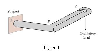
As mentioned earlier, several design iterations may be required in order to satisfy design and functional requirements for a component. Major steps involved in designing the structural member shown in figure 1 will illustrate the benefits to be gained by incorporating analyses into the CAD software.
These are some of the major steps required before the design of the structural member is finalized:
- The CAD designer creates an initial design for the structural member and submits an electronic file to an engineer for analysis.
- The engineer performs static finite element analysis on the structural member in order to identify areas of high stress gradients. The maximum load that the structural member could carry is used for the analysis.
Suppose that areas A, B and C are identified as having high stress gradients, and the maximum Von Mises stress is 100 MPa. It is required that the Von Mises stress should satisfy the maximum distortion strain energy criterion, with a factor of safety of 3.
The structural material is constructed from A36 steel with yield strength of 250 MPa. Because 100 MPa > 1/3 (250 MPa), a design iteration is required. - After the iteration, the maximum Von Mises stress is 70 MPa, therefore the design satisfies the maximum distortion strain energy failure criterion.
- The engineer performs fatigue analysis on the new design and determines that in order to avoid fatigue failure, the maximum allowable Von Mises stress should be 65 MPa.
- After iteration, the design is finalized and approved for production.
This example has not addressed all design analyses that may be required before the design is finalized. If the structural member operates in a corrosive environment, then the effects of corrosive wear should be considered. A good example of a structure which operates in a corrosive environment is the leg of an oil production platform.
If the structural member operates in high or low temperature environments, the effect of material property changes with respect to temperature should be considered, and a thermoelastic analysis should replace the static analysis. A good example of a structural member which operates in a high temperature environment is a tube which transports steam in a nuclear reactor plant. Such a tube could transport superheated steam at and 15 MPa pressure.
An example of a structural member which operates in a low temperature environment is the wing of a commercial airplane.
Assume that design iteration takes 24 professional hours to complete. At a professional billing rate of $100 per hour, the two iterations will cost $4800. If these design iterations could be eliminated by incorporating both engineering analyses into the CAD software, significant savings in cost could be achieved.
In practical terms, it may not be possible to implement all engineering analyses in CAD software. Furthermore, the CAD designer may need to be trained to perform the analyses correctly, with engineering supervision. Nevertheless, even if one engineering analysis is incorporated into the CAD software, significant reduction in the time and costs will be obtained.
CAD design software has been morphing into integrated CAD and CAE (Computer Aided Engineering) software within the past decade. A good example is Solidworks® by Dassault Systems, which was introduced in 1995. It retains the CAD portion of the software in eDrawings® and DraftSight® for the CAD designer who lacks the expertise for design analysis.
Another example is Autodesk®, which was introduced in 1982. It also integrates CAD and CAE functionality, but not to the same extent as Solidworks®.
– The CAD Chief

